At our community pool it is a popular destination for kids and adults who live in our neighborhood. Sometimes the water is just a tad colder than we’d like, or in the middle of summer, it might be like bath water, and not refreshing at all. What if there was a way to know the temperature before we went? What if there was a way where all homeowners in the neighborhood could check before going? But there is!

This project, I used open source software, and inexpensive hardware to create a unit to report the temperature once per hour to a UI running on a private server.
Project Goals
- Had to be CHEAP!!!
- Had to meet pool and public health safety guidelines for pool equipment
- Needed to be invisible – less chance kids will mess with it
- Needed a way to accurately measure the actual water temperature without making it obvious
- The unit needs to send data over a reliable link and via a reliable message transport (MQTT)
- Because it needs to be stealth, there’s no way to run it on solar, so needs to run a LONG time on a battery
- Needs to meet IP67 water proof rating and be completely sealed
Bill Of Materials
- 1 public pool! (permission from the HOA was obtained and granted for this project)
- ESP-F1 wifi wireless microprocessor
- DS18B20 waterproof temperature sensor
- 4x6cm prototype circuit board
- ESP-F1 breakout board
- 3 pin terminal block header
- Three 10K Ohm 1/4 watt resistors
- 10uF electrolytic capacitor
- self adhesive wifi dipole antenna (internal antenna)
- 3.3V LDO (Low Drop Out) regulator (NJU7223DL1-33)
- 26650 3.7 Lithium Ion battery
- 26650 battery holder
- hookup wire
- 4″x4″x3.9″ watertight enclosure
- four number 12 1.5″ flat head stainless steel screws
- double-sided self adhesive tape (industrial strength/weather proof)

Above, you can see the parts soldered on to the protoboard. The thing that looks like a TO-92 transistor on the green 3 pin terminal header was a temporary DS18B20 temperature sensor for testing. It was removed later and a waterproofed cabled DS18B20 sensor was put in its place just before deployment.

Here you can see the unit with a temporary ESP-12F module. The ESP-12F has a PCB trace antenna. That normally is OK, but I replaced the ESP-12F with the ESP-F1 which has identical pinout but instead of the onboard antenna, it has a small UfL connector. In the finished version, I installed a higher gain self-adhesive dipole antenna which connected to the ESP-F1 UfL connector, which provides a better radio circuit for sending data, yet remains stealth.

A large 26650 rechargeable Li-Ion battery powers the sensor electronics. Idle deep sleep current was actually measured at 35 microamps (uA). The sensor wakes up every hour, takes a reading, transmits the data to a server, and goes back to deep sleep and repeats the cycle. Wake time is 4 seconds or less and wake current is =< 180mA (milliamperes). The rough calculation given a conservative supply rating on the battery of 5000mAh, and the measured current in both the deep sleep and wake cycle should yield a runtime of approximately 533 days before the battery needs replacing/recharging.
I used the ESP-F1 instead of a dev board (like the wemos D1 or NodeMCU) because I needed this circuit to operate at microamps during deep sleep – that was critical for this stealth battery powered remote sensor. Those dev boards are unable to get down that low in the uA current range, so I had to stick with just the RF module and as few parts as possible. Here’s the circuit schematic:

I ordered THIS CASE from Amazon and installed the circuit into the case, drilling only one hole for a waterproof cable harness. The finished unit is about the size of a Rubik’s Cube:

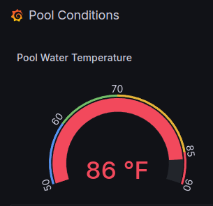
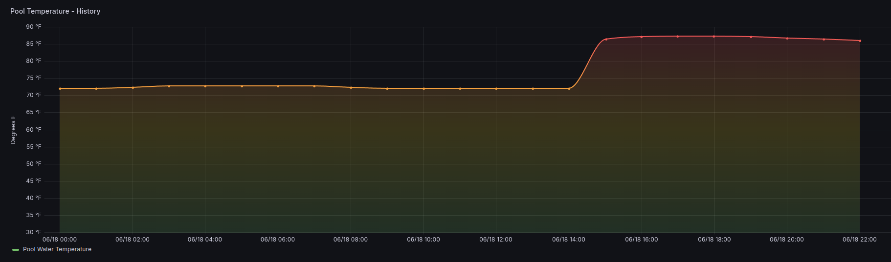
The onboard ESP-F1 publishes sensor values to an MQTT topic during wake. Once published, the data is picked up by a python script which inserts the data into an influxDB time series database. I have a Grafana docker container which has a configured public dashboard. On the dashboard is a temperature guage which reads the influxDB data measurements delivered over MQTT, and it is these measurements which provide the Grafana UI with data that powers the guage and historian graph.
Here are some pictures of the installation within the pool skimmer:

I countersunk the stainless steel screws for safety.

Now, it’s as simple as placing the skimmer cover back over the skimmer making sure the sensor probe is submerged in the water in the basket. The unit is already transmitting!

IT’S DONE!

Notes
esp8266 module is running Tasmota open source firmware. Apply these settings in the tasmota console:
SetOption65 1
SetOption56 1
SetOption36 0
Sleep 0
Rule1 ON System#Boot DO Delay 3; DeepSleepTime 3600 ENDON
Rule1 1
TelePeriod 300
DeepSleepTime 3600